
|
|
#1
 1st April 2013, 05:17 PM
|
||||
|
||||
|
Hi,
So today I actually could move the chassis to the garage! Yeah, it is a big step! And it is also and mostly thanks to my lovely girlfriend who really helped me to do so, I couldn't have done it all by myself. So I could try to fit the engine + gearbox in the chassis this afternoon. I built a "book" chassis, which means that the transmission tunnel is designed for a Type 9 gearbox. I have one, but some adaptations needs to be done to use it with the DOHC I will use in the Roadster. So, I wanted to try to fit the MT75 from the donor in the chassis, what looked possible to me, as it is a LHD chassis, so the narrow passenger footwell on the right side leaves enough space for the starter hump on the bell housing. It was not sure, but worth to try. And guess what? It actually fits! So it needs to be confirmed when everything is bolted and fitted, but I think it is a première : the MT75 gearbox actually fits in a LHD book (type 9) chassis. That could be interesting for those who, like me, drive "on the right side of the road" if they want or need to use a MT75 gearbox, they will not need to modify the original design as explained in the amendment section of this forum. IMG_4957.JPG There is just a little piece of alloy sticking out from the bell housing which touched CP17 on the driver (left) side and stop me to perfectly line-up the engine and gearbox with the chassis. I want to check with you if I can grind this bit off. If I can, everything should fit perfectly. It looks to me like it is just a bit from the cast when the bell housing has been fabricated, and does not have any utility. So grinding it off should not be a problem, but I need to be sure. Here is a picture the bit I want to grind-off on the left (driver) side, touching CP17. IMG_4962.JPG Here is picture of the same bit, but on the right side, so you can see better what it is. IMG_4966.JPG What do you guys think ? Can I grind it off without any bad consequences? Thank you very much in advance.
__________________
Sylvain Pictures of my completed Roadster https://www.flickr.com/photos/994983...7646799525542/ Build blog: http://vouchtroadster.blogspot.se/ https://cafrazx550.blogspot.com/ Last edited by voucht : 1st April 2013 at 05:24 PM. 
|
|
#2
1st April 2013, 10:01 PM
|
||||
|
||||
|
I think you'll find those are casting stubs, ie thats where the casting was poured in to.
__________________
Website http://www.talonmotorfabrication.co.uk/ Direct email phil@talonmotorfabrication.co.uk talonmotorfabrication@gmail.com Mobile office hours 07514098334
|
|
#3
2nd April 2013, 06:12 PM
|
||||
|
||||
|
Thank you very much for your reply Phil, it has been really helpful.
So I ground this casting stubs. After I did, I could place the engine/gearbox as I wanted. I have to confess that my euphoria from yesterday went down a little. Actually, the MT75 fits, but it is very close to CP17 on the driver (left) side, and the alternator of the DOHC is very close to rail D2 on the right side (which is not due to the MT75, but to the DOHC configuration). About 5mm on each side only. The picture on the left shows the gap between the bell housing and CP17 on the driver's side, and the picture on the right show the gap between the alternator and D2 on the passenger's side. Gap01.jpg With the engine movements/vibrations, I guess this gap is not big enough. To make sure, I drilled the engine mount in order to have the engine mounted correctly. When the engine is sitting on its rubber mounts, the bell housing is about 10mm from CP17, but the alternator touches D2 on the right side. The third picture below shows the maximum gap I can get when I strongly push the engine to the left. Gap02.jpg Even if a 10mm gap between the bell housing and CP17 is enough (what do you guys think?), I can't let the alternator touching D2. I thought about 2 solutions: 1 putting some dense vibration absorbent foam like the one used to make these thin racing motorbike saddles (EPDM foam, very good shock and vibration absorbent proprieties, and it is oil and fuel resistant). Will this be enough ? 2 I hope 10mm between the bell housing and CP17 is enough (I can still pad the area with the same foam), but on the alternator side, I'm thinking about removing D2 and weld a new bracing made of 2 tubes like on the sketches here under. Do you think it will be as efficient as D2? Which one of these two set-up do you find the best and the more adapted to what the chassis needs at this place? AlternativeD2.jpg Do you have other ideas to turn around the problem I have? All answers, comments and opinion, are welcome. Thank you very much.
__________________
Sylvain Pictures of my completed Roadster https://www.flickr.com/photos/994983...7646799525542/ Build blog: http://vouchtroadster.blogspot.se/ https://cafrazx550.blogspot.com/
|
|
#4
3rd April 2013, 10:48 AM
|
||||
|
||||
|
IMO the transmission clearance is OK. Regarding the alternator, consider switching to a smaller one or fabricating a bracket tat relocates it.
P.S. Is the clutch fork in the transmission now? On Type 9 it's the part with least clearance to the chassis.
__________________
Albert Haynes Roadster FAQ | Haynes Builder Locations Gallery, build thread in Lithuanian / via Google Translate. Last edited by alga : 3rd April 2013 at 10:51 AM.
|
|
#5
3rd April 2013, 12:01 PM
|
||||
|
||||
|
Hi Sylvain the tabs you ground off are called Sprue's and yes serve no purpose once casting is complete.....you will not really know whether your clearance is enough until firing up the engine to see if it torque rocks, I know mine has less clearance on one side but does not touch or vibrate, if yours does "rock" a lot you could upgrade the engine mounts to stiffer ones, I know the land rover ones are very stiff....I think it looks ok from what I can see.....good to have you back on the forum by the way.
|
|
#6
3rd April 2013, 10:13 PM
|
||||
|
||||
|
Thank you so much Albertas and Kevin for your replies.
So I'm not worrying about the clearance between the bell housing and CP17, thanks for that. I will anyway buy these Range Rover stiff engine mounts to be sure. Regarding the alternator, today, I modified the big bracket. This is a one piece bracket for: - the drive belt tensioner, - the alternator, - the power steering pump. Alternator01.jpg As shown above, the upper part of the bracket and the drive belt tensioner attached on it stopped me to push the alternator toward the engine block. I must get rid of them if I want to use this alternator. So, I dared removing the upper part which means I can no longer use the original belt tensioner (I also removed the lower part : power steering pump mounting points) Pic1: cutting the power steering pump mounts Pic2: lower part of the big bracket is cut off. Pic3: the part below the black line is the alternator mount I want to keep. above the black line is the belt tensioner mount I want to cut off Pic4: upper part of the big bracket is cut off. Alternator02.jpg It left the bracket only with the alternator mounting points. Alternator03.jpg This way, I can get a gap of 53mm between the alternator and D2, which is even more than I expected, so I'm satisfied with that. Pic1: the alternator can now be much closer to the engine. Pic2: this thin metal strip is just here to simulate the part I need to be able to tense the new belt Pic3: 43mm gap between the alternator and D2 when in position with the metal strip Pic4: 53mm gap between the alternator and D2 when the alternator is completely against the engine block. Alternator04.jpg I think the gap between the alternator and D2 is now wide enough to allow me to push back the alternator outwards for tensing the belt. Am I right ? Now, I need to find a way to be able to tense the belt (I will need to buy a shorter belt, but it shouldn't be a problem to find), as I can no longer use the original belt tensioner. I can either use the adjustment strip from my SOHC, make my own, but I will try to install this kind of part, which will allow me to tense the belt easily. Alternator035.jpg I will complete this post when the alternator is definitely fitted. If you see anything wrong with this set up, please feel free to let me know, that is the main reason why I keep on publishing pictures and descriptions. Thank you very much.
__________________
Sylvain Pictures of my completed Roadster https://www.flickr.com/photos/994983...7646799525542/ Build blog: http://vouchtroadster.blogspot.se/ https://cafrazx550.blogspot.com/
|
|
#7
4th April 2013, 07:45 AM
|
||||
|
||||
|
Nice, little alternator bracket - I like it
 Good work. Good work. And it's lightweight too 
__________________
Lucas ZX9R BEC Haynes Roadster - build cost so far: £1125 My build thread "Whatever you can do or dream you can, begin it. Boldness has genius, power, and magic in it." J.W.Goethe
|
|
#8
6th April 2013, 06:36 PM
|
||||
|
||||
|
I like your new avatar, Łukasz, it looks like you're approving of every thread you post in :-)
__________________
Albert Haynes Roadster FAQ | Haynes Builder Locations Gallery, build thread in Lithuanian / via Google Translate.
|
|
#9
9th August 2013, 09:58 PM
|
||||
|
||||
|
End of the alternator saga. Not that it is extremely intersting, but I though it could be of some help to DOHC users.
After having fitted the tensioner from the Pinto I have in the bottom of my garage, I was not totally staisfied. 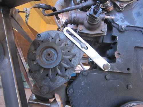 IMG_5241 par Voucht71, sur Flickr So, today, I fitted the part I was talking about a couple of posts above. Some adaptations were needed (eyes are 11mm diam. and alternator bolt is M8 and engine block threaded hole is M10, so I had to insert bushes). 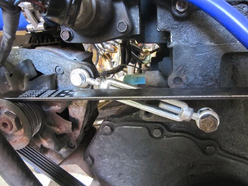 2013-08-09_16-42-17 par Voucht71, sur Flickr I'm very happy with the result and tensioning the belt is now so very easy. More details on my blog (comments are not in English yet, but I'm working on it )
__________________
Sylvain Pictures of my completed Roadster https://www.flickr.com/photos/994983...7646799525542/ Build blog: http://vouchtroadster.blogspot.se/ https://cafrazx550.blogspot.com/
|
 |
| Thread Tools | |
| Display Modes | |
|
|


 Linear Mode

